Here are four diagrams of my now expired OO Chorley Garage Layout.
The wall poster below was produced to remind me of what it all looked like. The top part was the upper level, the middle the spiral and the bottom the lower. It includes the heights of the track above the bottom.

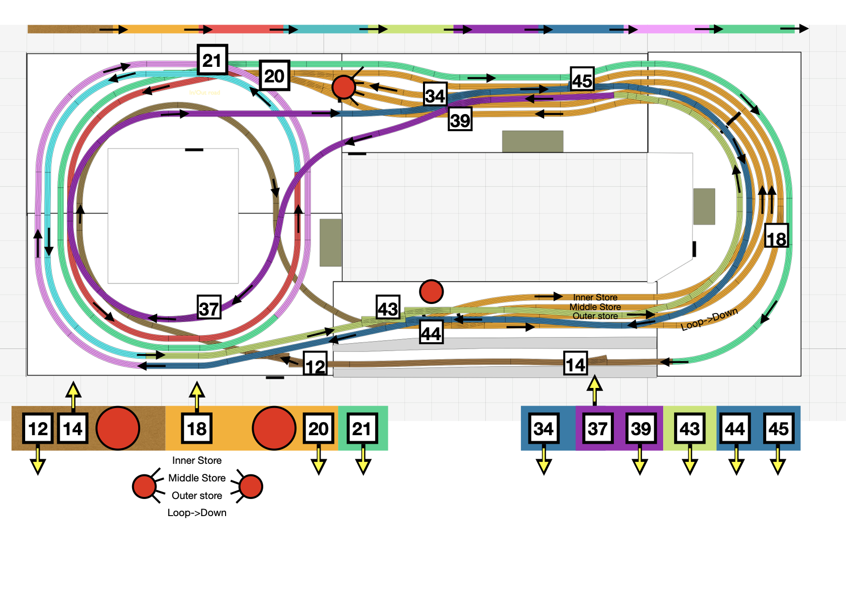
The following chart, also created for the wall, shows a full circuit around the layout. I was able to run three trains chasing one another and they took three to four minutes.
The dark brown at the bottom of the image is the station, follow that going clockwise (initially) until you get back to it. The colours do follow a sequence.

Because there were various other routes around the layout, for example two circuits on the top and two circuits on the bottom, plus the three routes through the store, I produced the chart below to remind myself which switches needed to be set in order to go back to the full circuit. That sounds a good idea but there were many derailments and crashes from me failing to remember to change them.
The last chart is one of several of the schematics of the electrics. This one shows the main power units feeding the track and accessories.

At the time of writing I have a track plan for my new, TT120, layout, but no boards as yet and and evolving plan for the electrics and electronics required.